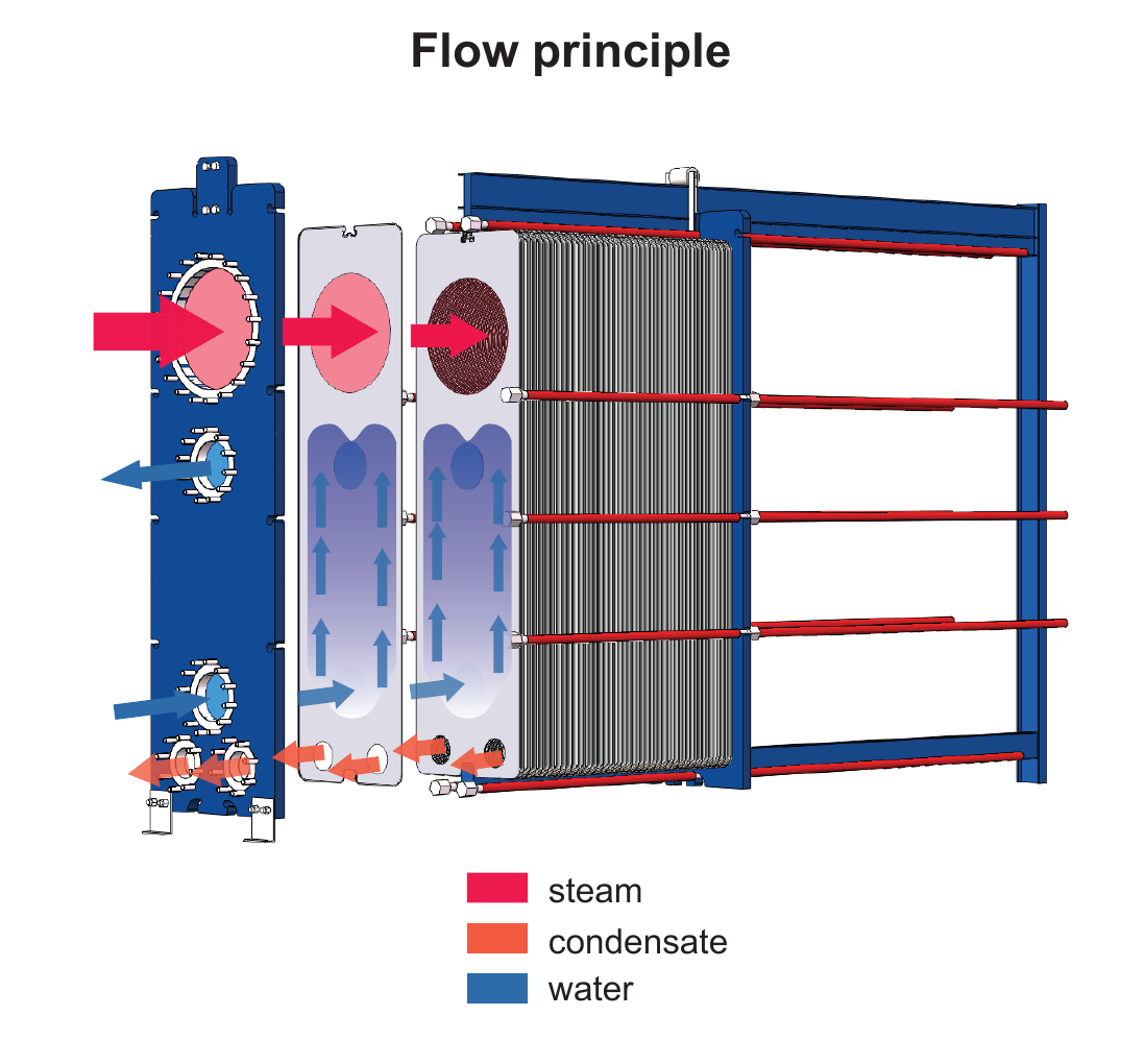
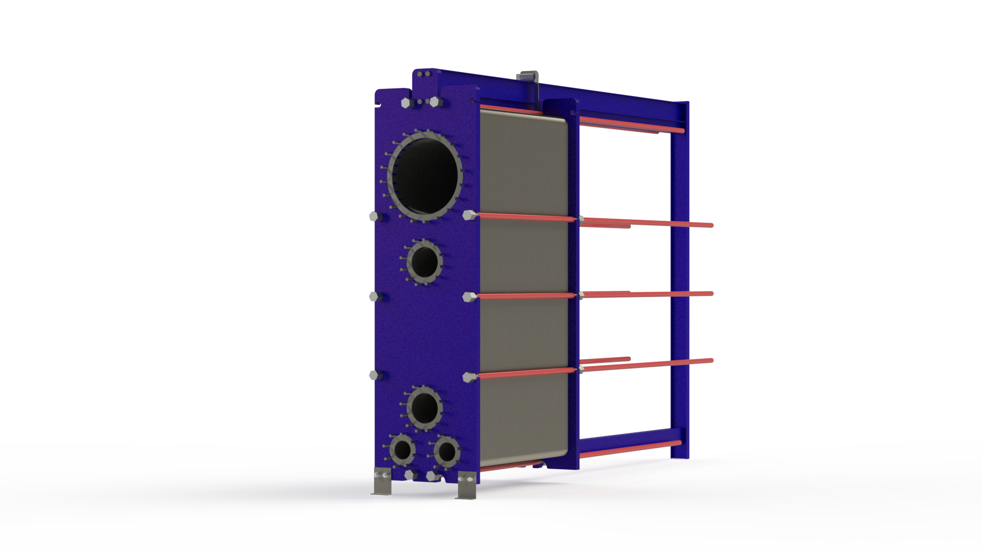
Plates are welded in pairs to form cassettes. Vapour condenses in the welded large-gap channel while cooling water flows through the gasketed narrow channel. A centrally positioned large vapour inlet, lower condensate outlets and symmetric cooling-water connections support stable distribution and low vapour-side pressure loss.
Product imagery is paired with technical context so buyers and engineers can understand construction, flow path and configuration—not just the exterior.
01
Dedicated vacuum-condensation flow path
The large upper vapour inlet feeds welded large-gap channels; condensate leaves at the bottom while cooling water travels through alternating gasketed channels.
Models & technical data
Compare models and published specifications.
Compare the published model dimensions and technical values from the product datasheet.
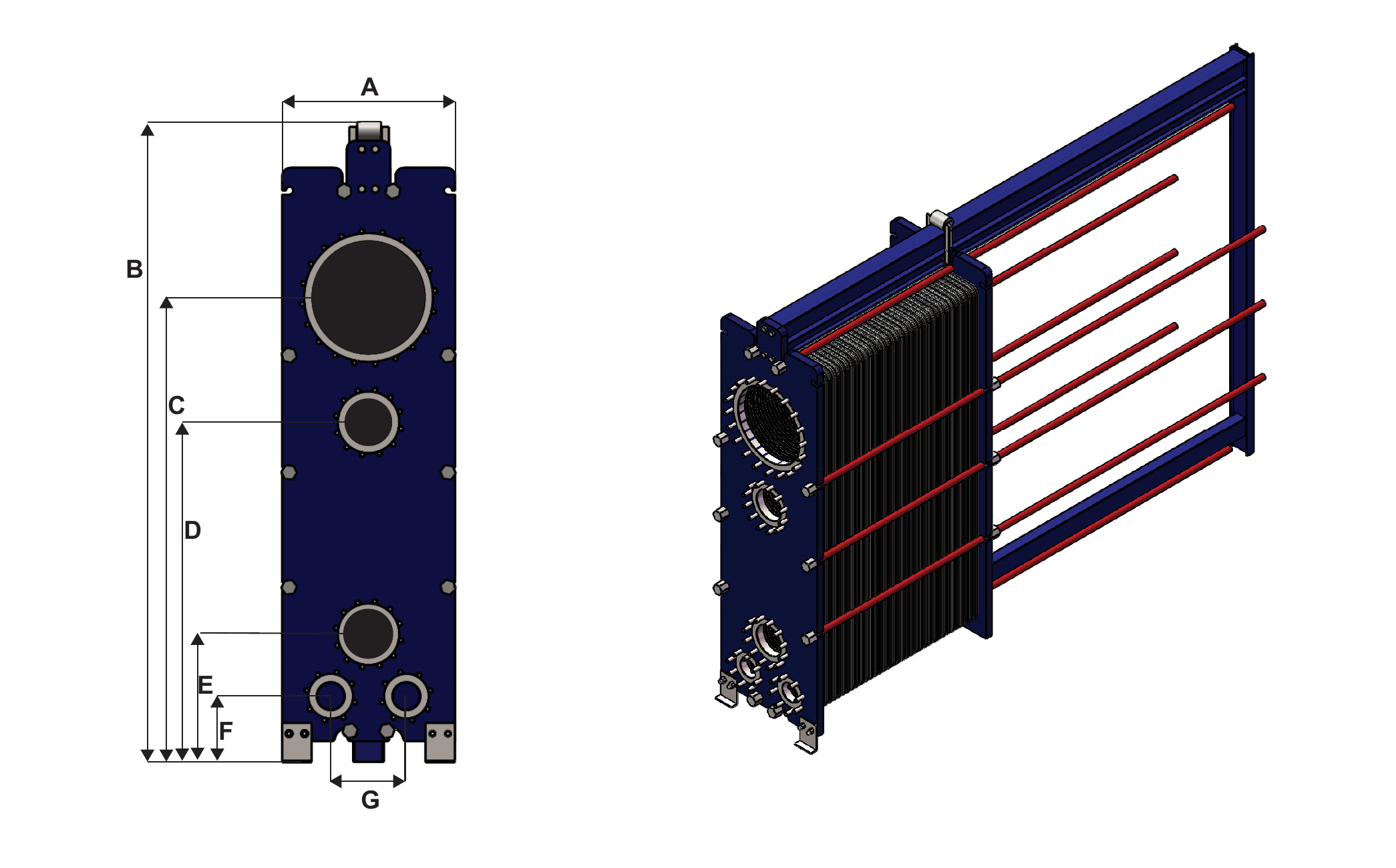
Published condenser GPHE dimensions from the supplied technical datasheet. Final cassette count, frame length, connection class, material and operating limits are confirmed for the selected duty.
Dimensions are for reference only. Final dimensions are subject to the approved order drawing. HEXNOVAS reserves the right of final interpretation.
Model details
AC400-W
HEXNOVAS Condenser Gasketed Plate Heat Exchangers
Product configurationDimension drawing
A (mm)
617
B (mm)
2,217
C (mm)
1,658
D (mm)
1,215
E (mm)
457
F (mm)
236
G (mm)
270
Plate type
Semi-welded
Free channel
11 / 3 mm
Plate material
304 / 316L stainless steel; titanium option by duty
Field and ring gaskets
NBR / EPDM / FKM
Maximum design pressure
10 bar / 145 psi
Maximum design temperature
160°C / 320°F
Dimensions are for reference only. Final dimensions are subject to the approved order drawing. HEXNOVAS reserves the right of final interpretation.
Designed around performance, integrity and serviceability.
Large vapour channels support condensation under vacuum with very low pressure drop
Optional sub-cooling of condensate and non-condensable gases
Heat-transfer area can be adjusted by changing the cassette count
Openable construction supports inspection and cleaning
Product configuration
Structure and material options.
Available configurations
AC400-W and AC600-W semi-welded platforms
Vacuum condensation with optional condensate sub-cooling
Cassette count adjustable within frame limits
Metal-lined or stainless-steel flange connections
Material options
304 or 316L stainless-steel heat-transfer plates
Titanium plate option for seawater cooling duties
NBR, EPDM or FKM field and ring gaskets
Epoxy-painted carbon-steel frame and pressure plates
Typical applications
Where this exchanger fits.
01
Biotechnology and pharmaceutical processing
02
Chemical and process industries
03
Energy, utilities and heat recovery
04
Food, beverage, marine, pulp-and-paper and wastewater duties
Selection information
What our engineers need from you.
Provide vapour composition and load, condensation pressure or vacuum, cooling-medium flow and temperatures, allowable vapour-side pressure drop, sub-cooling requirement, non-condensable gas content, material requirements and fouling tendency.
Frequently asked questions
Key questions before product selection.
How does Condenser Gasketed Plate Heat Exchangers work?
Plates are welded in pairs to form cassettes. Vapour condenses in the welded large-gap channel while cooling water flows through the gasketed narrow channel. A centrally positioned large vapour inlet, lower condensate outlets and symmetric cooling-water connections support stable distribution and low vapour-side pressure loss.
What information is required to select the right product?
Provide vapour composition and load, condensation pressure or vacuum, cooling-medium flow and temperatures, allowable vapour-side pressure drop, sub-cooling requirement, non-condensable gas content, material requirements and fouling tendency.
Which materials and configurations are available?
304 or 316L stainless-steel heat-transfer plates; Titanium plate option for seawater cooling duties; NBR, EPDM or FKM field and ring gaskets; Epoxy-painted carbon-steel frame and pressure plates
How is the final product size confirmed?
The final size is confirmed by thermal calculation using flow rates, inlet and outlet temperatures, allowable pressure drop, design pressure and fluid properties.
Product documentation
Catalogue and technical downloads.
Use the published catalogue for product-range reference. Final dimensions, ratings and materials are confirmed for the selected model and operating duty.