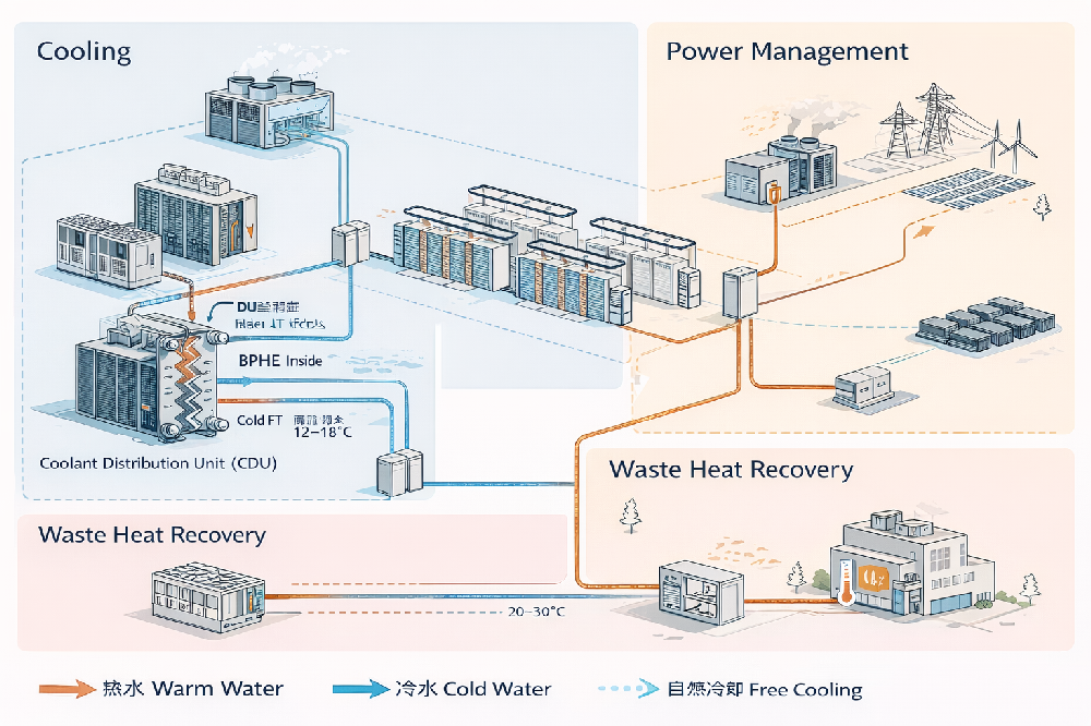
Modern data centers are energy systems. Heat exchangers act as the thermal interface between IT liquid loops, facility water, free cooling equipment, and waste heat reuse networks.
Modern data centers are no longer simple server rooms. They are complex energy systems integrating cooling, power management, and waste heat recovery. As shown in the system diagram, heat exchangers form the core thermal interface between IT equipment and external energy infrastructure.
Rather than acting as isolated components, heat exchangers operate as thermal bridges, connecting internal liquid cooling loops with facility water systems, free cooling units, and heat reuse networks.
1) Cooling System — BPHE (Brazed Plate Heat Exchanger) Inside CDU
In the cooling section, heat exchangers are located inside the Coolant Distribution Unit (CDU). The BPHE separates two independent circuits:
- IT coolant loop (directly connected to servers)
- Facility water loop (chilled water or cooling water)
The BPHE transfers heat from server liquid to building water without mixing fluids.
Illustrative design parameters — verify against the selected CDU and site duty
- IT loop inlet: 30–45°C
- IT loop outlet: 20–30°C
- Cooling capacity per BPHE: 200–1500 kW
- Design pressure: 10–25 bar
- Approach temperature: 2–4 K
The heat exchanger separates the IT and facility fluid circuits and transfers heat between them. Hydraulic separation does not itself provide electrical isolation; any electrical isolation or dielectric requirements need a separate system-level assessment.
2) Free Cooling — Heat Exchanger as Environmental Interface
In the free cooling section, heat exchangers connect internal cooling loops to dry coolers, cooling towers, or ambient water sources. Instead of using chillers, the system uses outside air or water directly.
Illustrative free-cooling scenario — not an annual performance guarantee
- Cold water temperature: 12–18°C
- The existing 40–70% annual free-cooling figure is illustrative only; available hours depend on climate, supply-water temperature, approach temperature and load profile.
- The existing 15–30% energy-saving figure is scenario-dependent, not a universal outcome. Assess it against the baseline cooling architecture, climate, controls and operating hours.
In this scenario, the heat exchanger becomes the boundary between the data center and the natural environment.
3) Waste Heat Recovery — Heat Exchanger as an Energy Export Device
The lower part of the diagram shows how heat exchangers enable waste heat reuse. Recovered warm water is transferred to office buildings, district heating systems, or domestic hot water networks.
Illustrative heat-recovery scenario — not verified site performance
- Warm water temperature: 30–55°C
- The existing 6000–8000 annual reuse-hour example depends on simultaneous heat availability and useful demand, temperature level and operating schedule.
- The existing up to 40% CO₂-reduction example is illustrative only; the result depends on the displaced energy source, electricity emissions, useful heat delivered and baseline system.
In this role, the heat exchanger transforms the data center from a pure energy consumer into an energy supplier.
Engineering Conclusion
From cooling to free cooling and heat recovery, heat exchangers are no longer auxiliary devices. They act as:
- Thermal interfaces
- Energy transfer hubs
- System integration components
In next-generation data centers, heat exchangers are not just part of the cooling system — they are core infrastructure for digital energy management.
FAQ — Heat Exchangers in Data Centers
Which exchanger type is commonly used inside a CDU?
Brazed plate heat exchangers are a compact option for CDUs. Their suitability depends on the selected system architecture, fluid quality, pressure drop and service requirements.
Reasons:
- Compact size for rack-level or room-level integration
- High heat transfer coefficient
- Low approach temperature (2–4 K)
- High pressure capability (10–25 bar typical)
- The brazed core avoids plate-pack gaskets, but this does not eliminate leakage risk at joints or connections.
For larger duties, including the existing approximately 1.5 MW example, GPHE or plate-and-shell options may be considered. Capacity alone is not a technology-selection threshold.
When is a gasketed PHE considered for a data center?
A Gasketed Plate Heat Exchanger (GPHE) is typically used when:
- Larger capacities, such as the existing 1–2 MW example, assessed with flow, pressure drop and maintenance needs
- Maintenance accessibility is required
- Water quality may require mechanical cleaning
- Long-term serviceability is critical
GPHE units allow plate removal and cleaning, making them suitable for large central plant installations.
Are shell-and-tube exchangers used in data center cooling?
Yes, but less frequently. They are used when:
- Extremely high reliability is required
- Water quality is poor
- Fouling risk is high
- Very large flow rates exist
Shell-and-tube footprint and approach temperature should be compared on the same duty, pressure-drop allowance, fouling basis and maintenance requirements; lower efficiency is not inherent to the architecture.
Plate heat exchangers may suit space-constrained duties; the final selection requires the same thermal and hydraulic comparison.
Which exchanger types can support building-side integration?
Common options:
- Gasketed plate heat exchangers — an option for serviceable building-side installations
- BPHE — for modular or smaller systems
- Welded plate — for higher pressure or glycol concentration
Selection depends on water chemistry, maintenance strategy, approach temperature, and capacity.
- GPHE / PSHE for district heating integration
- Plate-and-shell for higher pressure networks
- Double-wall exchangers when separation safety is required
Pressure class must be checked against the actual system and selected equipment. The existing 16–25 bar reference is illustrative, not a general district-heating requirement.
- Very high heat transfer efficiency
- Low approach temperature (critical for liquid cooling)
- Compact footprint
- Modular scalability
- Lower refrigerant/coolant charge
- Easier integration with energy recovery systems
Which materials are discussed for data center heat exchangers?
Plates: 316L (most common), 304 (low corrosion), Titanium (special water)
Brazing: Copper (standard), Nickel (aggressive fluids)
Gaskets (for GPHE): EPDM (water), NBR (oil), FKM (high temperature)
Efficient heat exchanger design reduces chiller load, improves free cooling window, enables higher supply temperatures, and supports waste heat reuse — directly lowering cooling energy consumption and improving PUE.
In liquid-cooled data centers, the heat exchanger is one of the primary determinants of thermal efficiency.
- Cooling capacity (kW or MW)
- Approach temperature
- Pressure drop limitations
- Water chemistry
- Maintenance access
- Redundancy requirements
- Future scalability
Proper sizing is critical because undersizing increases approach temperature, while oversizing increases capital cost.
When might double-wall separation be required?
Double-wall heat exchangers may be required when:
- There is risk of cross-contamination
- The circuits require enhanced separation and leak detection as specified by the project
- Compliance standards demand leak detection
They provide enhanced safety but increase cost and footprint.
Pillow Plate Heat Exchangers in Data Centers
Pillow plates may be considered in data-center systems where their panel geometry and rated performance fit the duty. No market-prevalence claim is established here.
Potential pillow plate applications, subject to project-specific thermal and mechanical assessment, include:
- Rear door heat exchangers (RDHx)
- Immersion cooling tank walls
- Waste heat recovery modules
- Structural cooling panels
Where Pillow Plates Are Applied
Typical placement
- Rear-door cooling panels: large surface area, uniform distribution, low pressure drop
- Immersion tanks: large welded panels integrated into tank walls or internal cooling surfaces
- Heat recovery skids: warm water transfer modules with large flat heat transfer surfaces
How to Assess Pillow Plate Suitability in a CDU
When Pillow Plate Is the Right Choice
- Large flat surfaces are available
- Structural integration is required
- Moderate heat flux density is acceptable
- Fully welded construction is preferred
- Fouling tolerance is needed
BPHE, GPHE and pillow plate options should be selected for the actual architecture and duty. These examples do not establish market prevalence or equivalent performance.
| Factor | BPHE | Pillow plate |
| Compactness | Depends on plate pack and duty | Depends on panel arrangement and duty |
| Heat transfer coefficient | Depends on fluids, flow and corrugation | Depends on fluids, flow and panel geometry |
| Approach temperature | The existing 2–4 K example requires duty-specific rating | Requires duty-specific rating |
| Size per duty | Compare at the same duty and pressure drop | Compare at the same duty and pressure drop |
| Pressure capability | Verify the selected model rating | Verify the selected panel and assembly rating |