
Available configurations
- Liquid-to-liquid spiral exchanger
- Vapor condenser and selected gas duties
- Removable or welded cover arrangements
- Horizontal or vertical project layouts
SPIRAL technology
Fully welded single-channel heat exchangers for fouling fluids, sludge, slurries, viscous media and industrial heat recovery.
Working principle
Two metal plates are rolled into separate concentric spiral passages. One fluid flows from the center toward the outside while the second counter-flows in the adjacent channel. Each medium follows one continuous path, so a local restriction increases velocity rather than allowing flow to bypass the fouled area.
Engineering explained
Product imagery is paired with technical context so buyers and engineers can understand construction, flow path and configuration—not just the exterior.
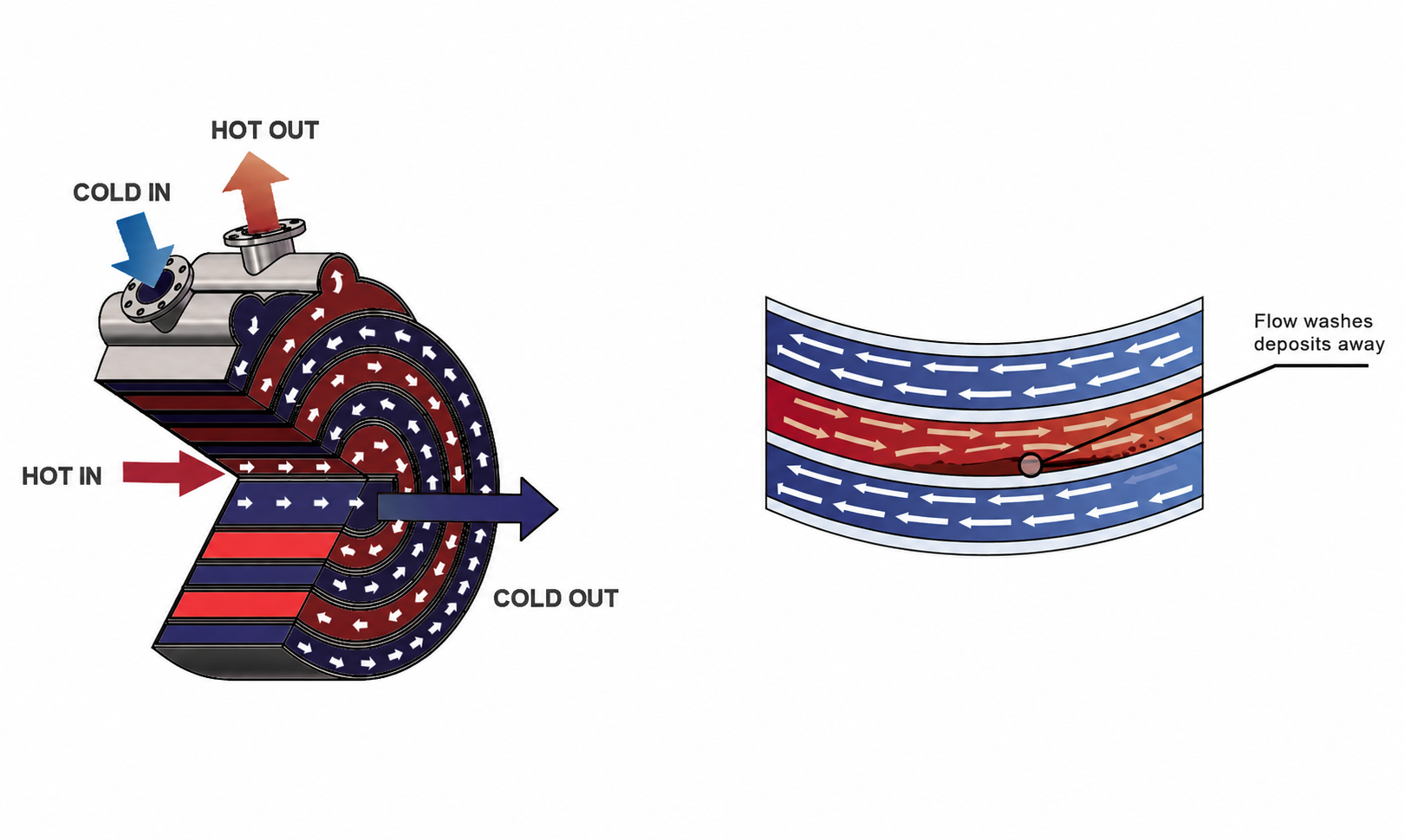
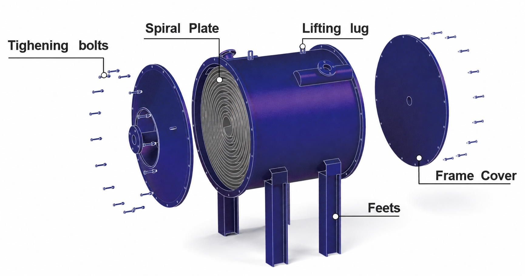
The welded spiral core creates two isolated continuous passages. Covers, nozzles and supports are configured around pressure, cleaning access and installation requirements.
Hot and cold media travel in opposite directions through adjacent spiral channels. The single path maintains velocity and reduces stagnant zones in fouling service.
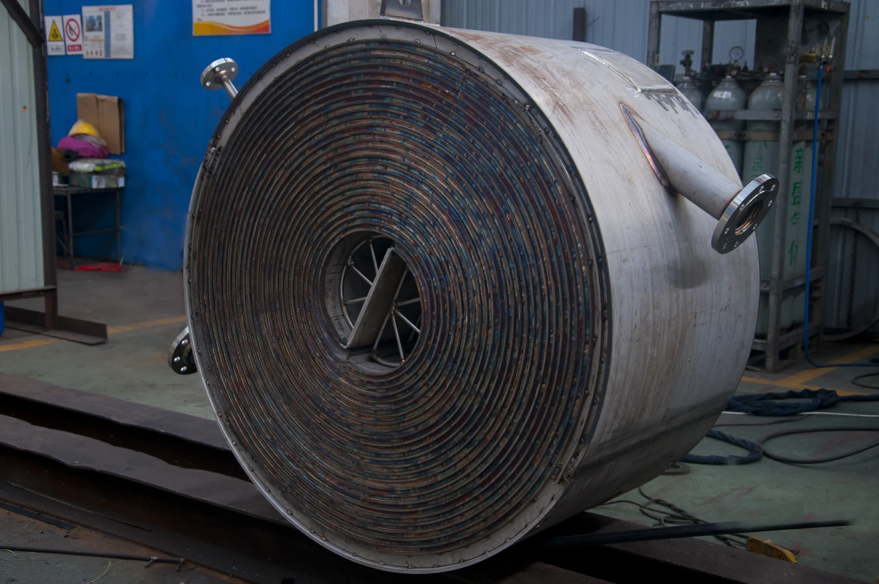
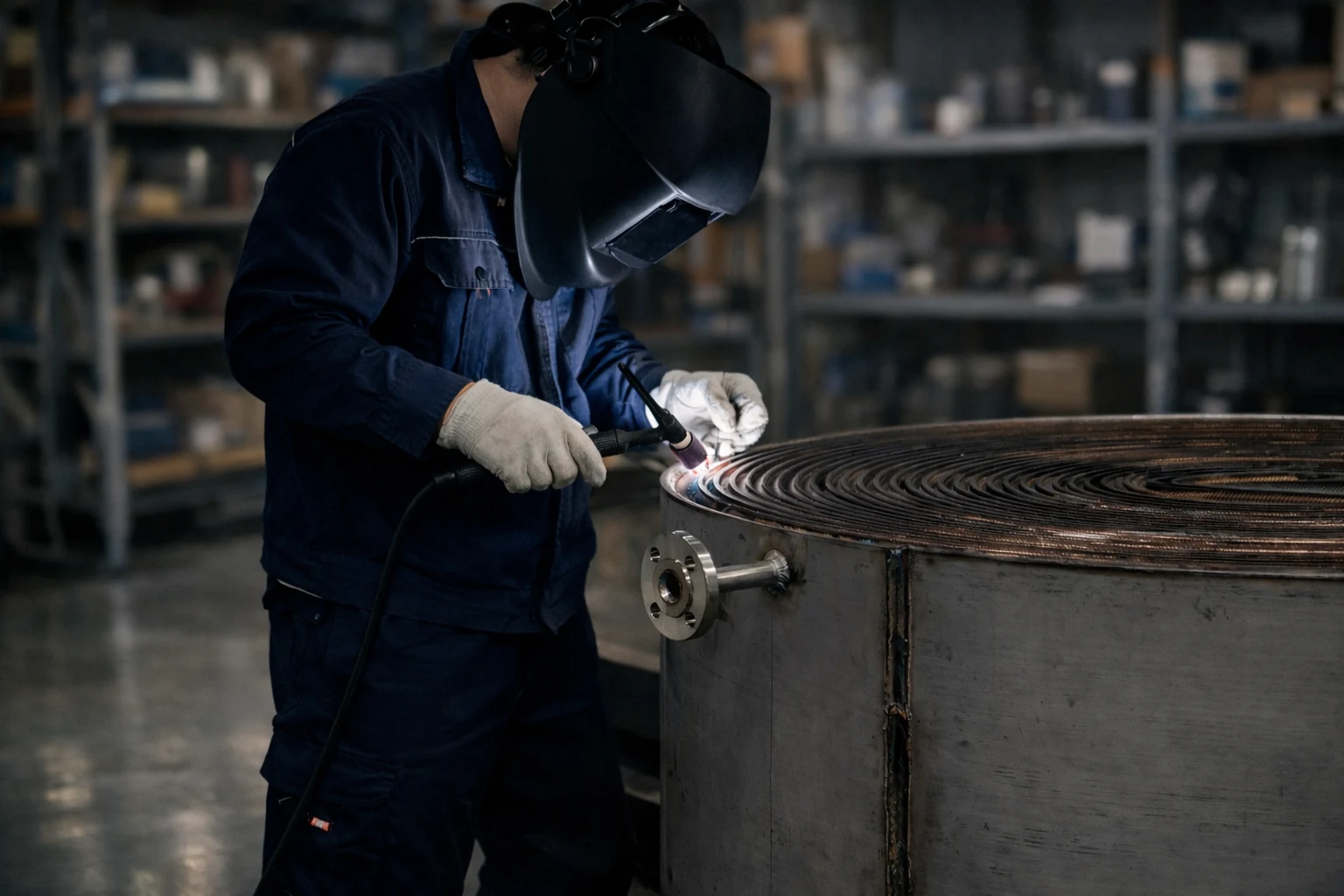
A real welded spiral core shown during production, before the removable cover and final external finishing are completed.
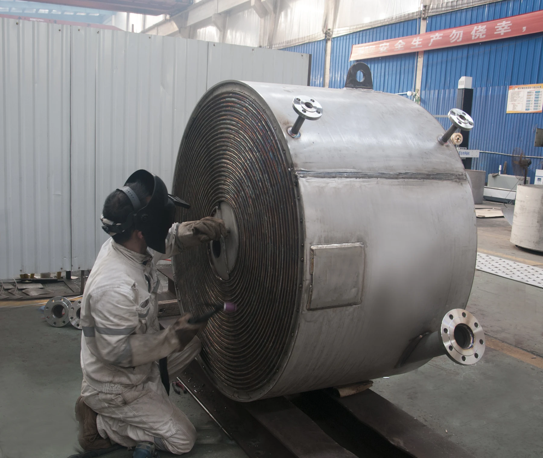
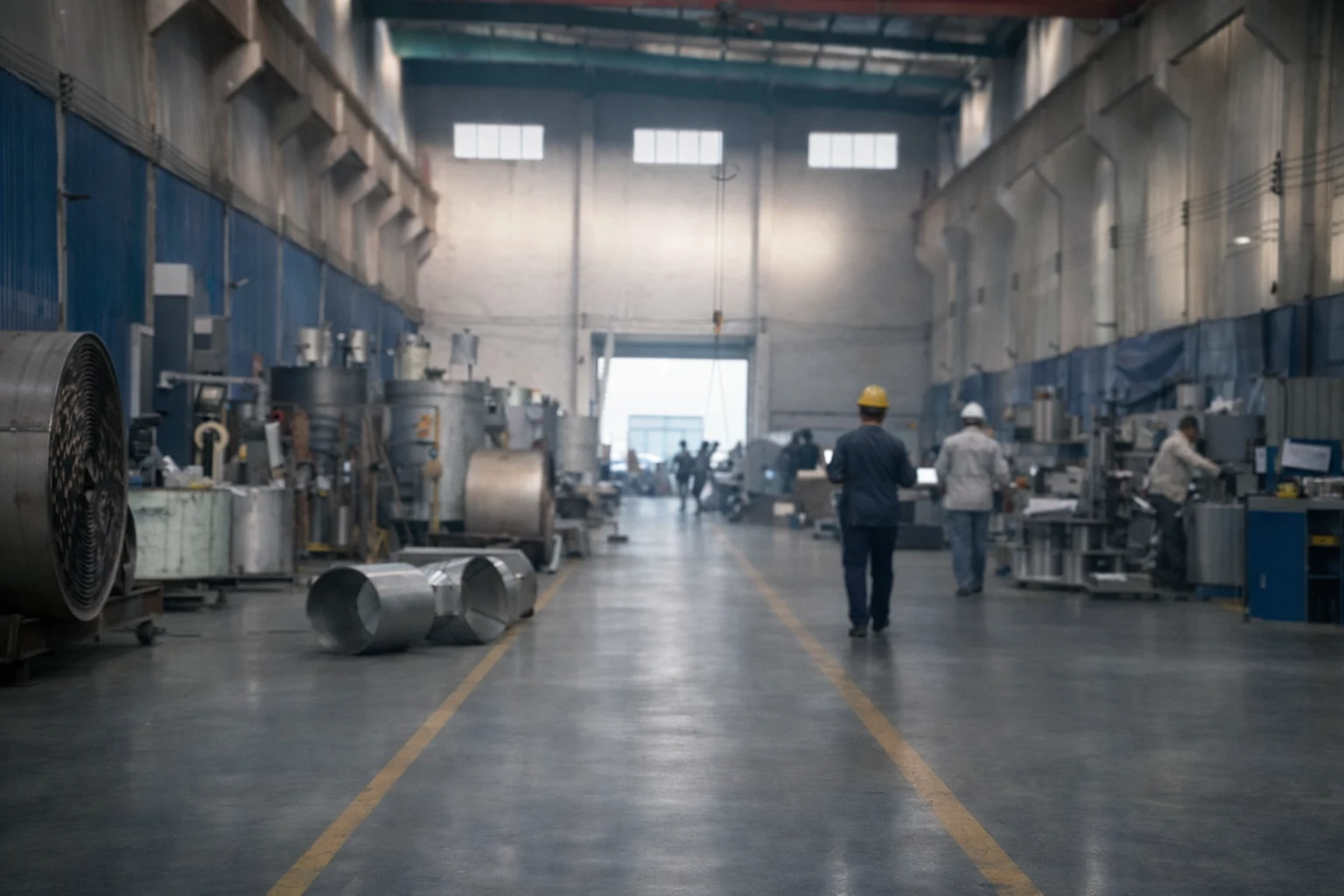
Workshop fabrication is completed around the spiral channel geometry, connections and agreed inspection requirements.
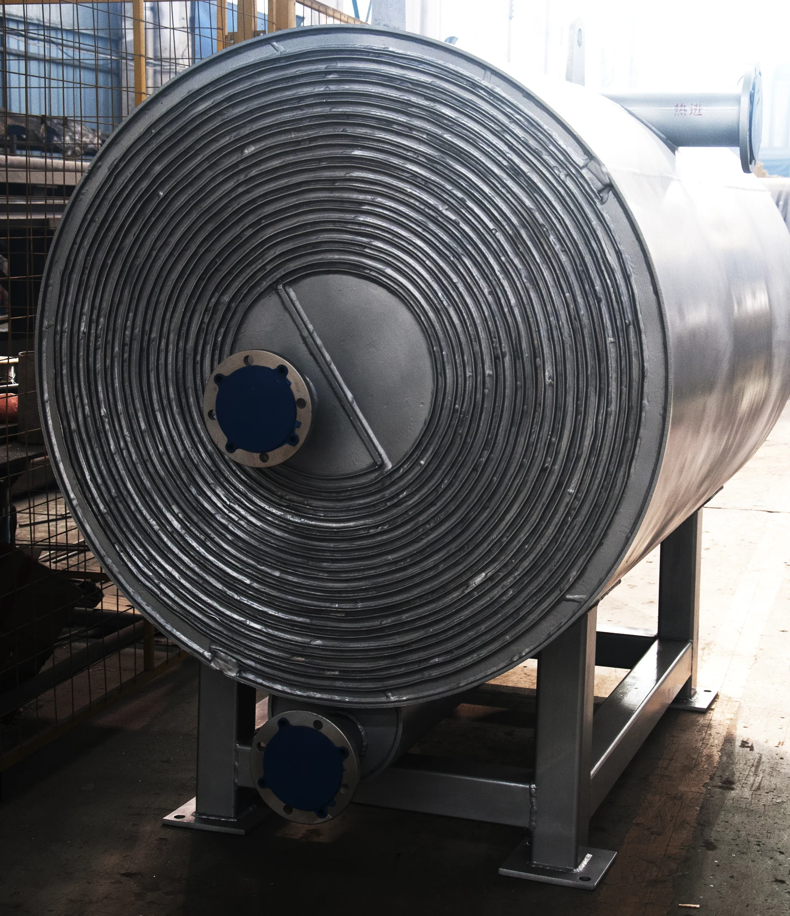
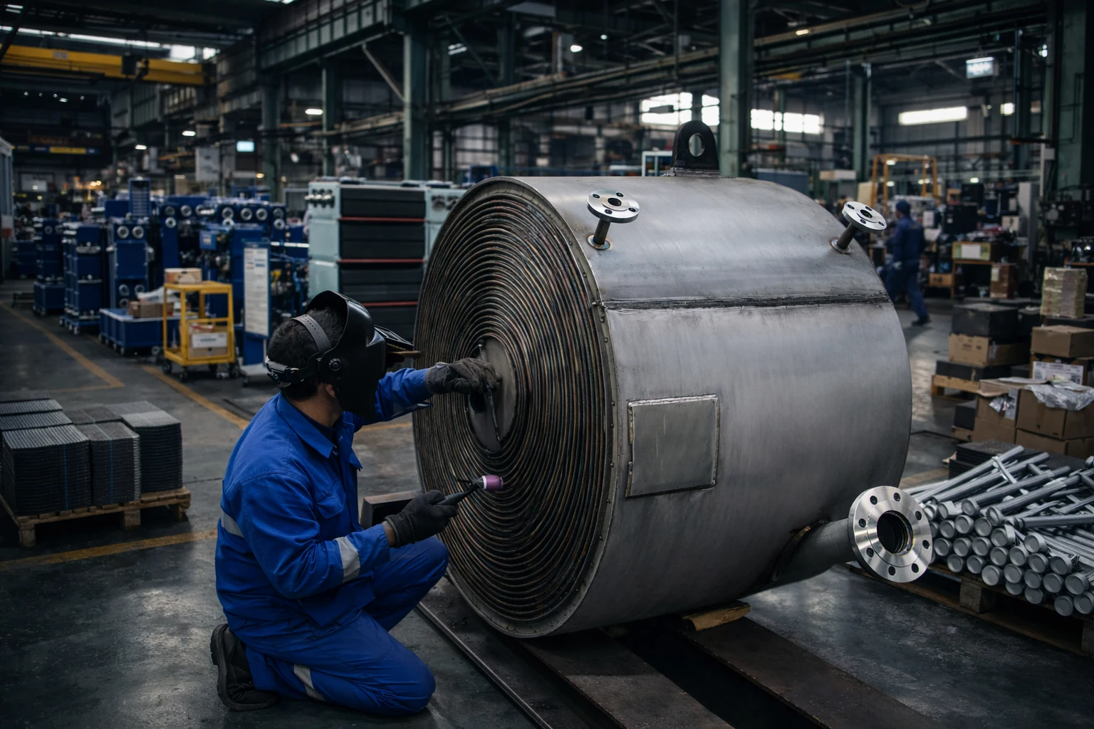
A finished stainless-steel spiral heat exchanger with its spiral channel face, shell, supports and process connections visible.
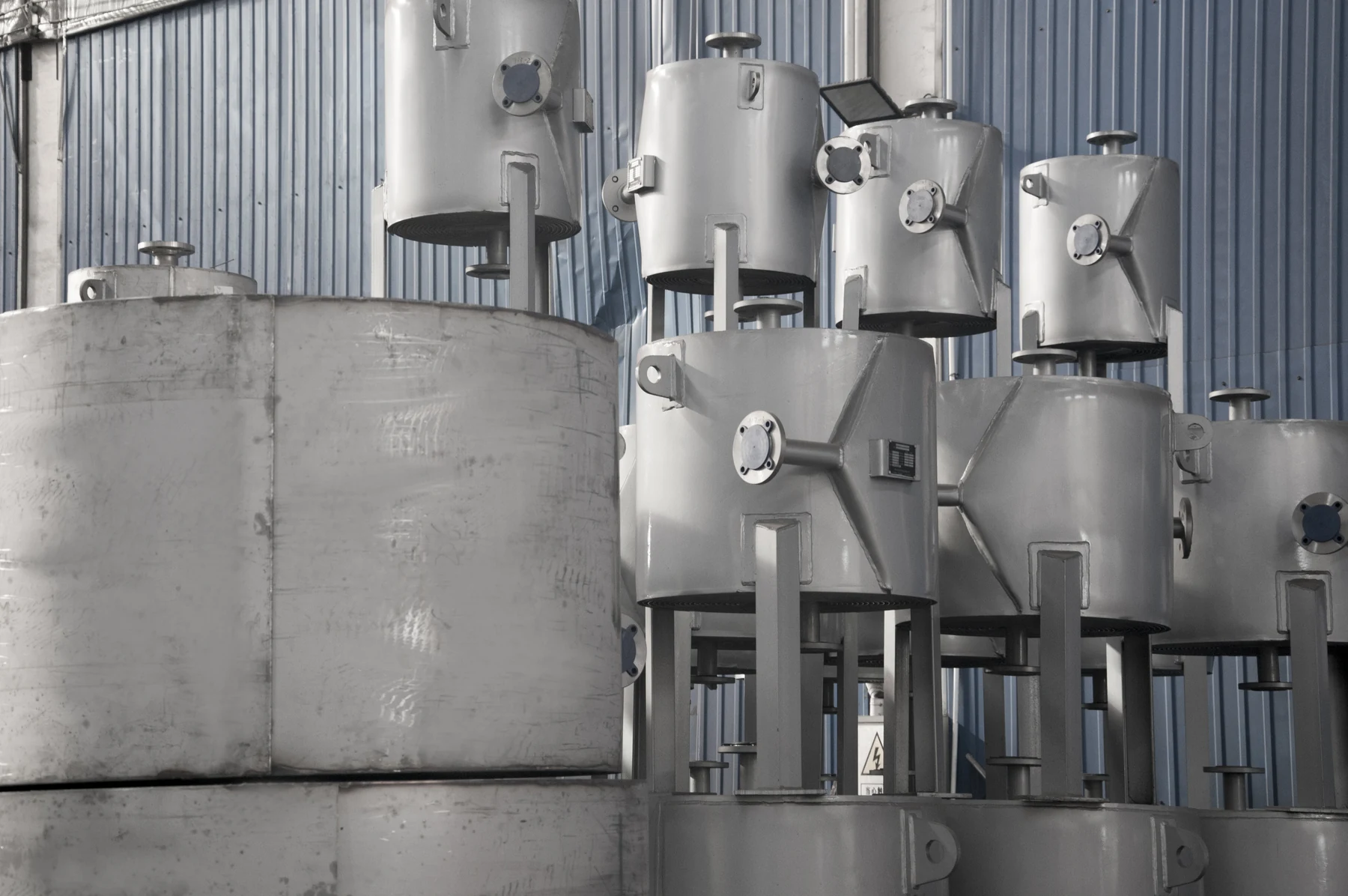
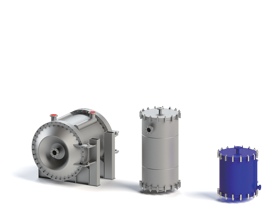
Completed vertical units demonstrate the range of project-specific vessel, nozzle and support arrangements available.
Why this technology
Product configuration
Typical applications
Selection information
Provide both fluid compositions and flow rates, inlet and outlet temperatures, allowable pressure drop, viscosity, solids or fiber content, particle size, fouling tendency, cleaning method, design conditions and material requirements.
Frequently asked questions
Two metal plates are rolled into separate concentric spiral passages. One fluid flows from the center toward the outside while the second counter-flows in the adjacent channel. Each medium follows one continuous path, so a local restriction increases velocity rather than allowing flow to bypass the fouled area.
Provide both fluid compositions and flow rates, inlet and outlet temperatures, allowable pressure drop, viscosity, solids or fiber content, particle size, fouling tendency, cleaning method, design conditions and material requirements.
Carbon steel, SS304 and SS316L; Duplex 2205, 904L, 254 SMO and AL6XN; Titanium and nickel alloys after corrosion review
The final size is confirmed by thermal calculation using flow rates, inlet and outlet temperatures, allowable pressure drop, design pressure and fluid properties.
Product documentation
Use the published catalogue for product-range reference. Final dimensions, ratings and materials are confirmed for the selected model and operating duty.
Discuss this product