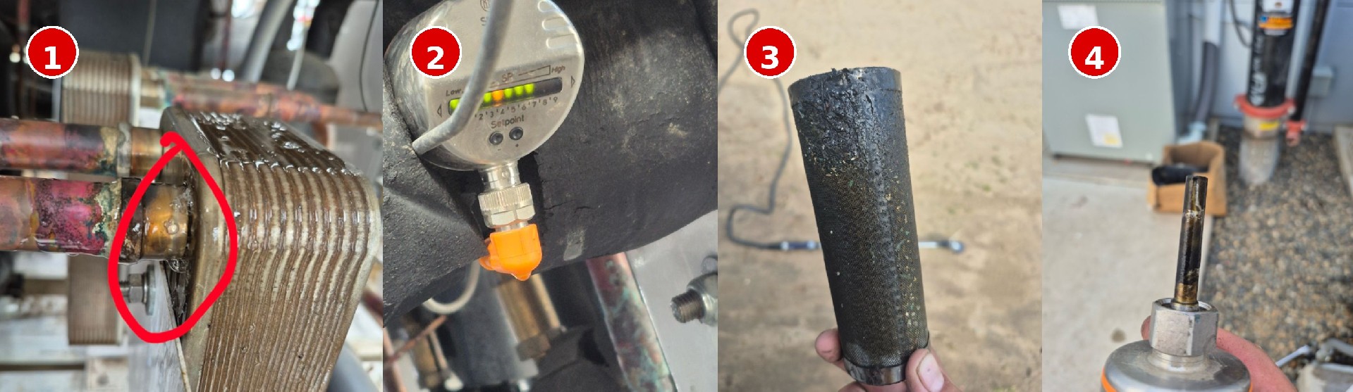
A brazed plate heat exchanger (BPHE) used in a vapor injection heat pump system developed leakage at the nozzle connection region. Field inspection revealed significant contamination within the refrigeration circuit.
These hydraulic abnormalities indicate that the exchanger was operating under non-design flow conditions prior to failure.
When refrigerant mass flow is restricted, compressor discharge temperature increases. Reduced heat transfer efficiency leads to elevated condensing pressure, commonly referred to as a High Head condition.
Flow restriction often represents the initiating disturbance in the failure sequence.
High head pressure directly increases condensing temperature. As condensing temperature rises, the internal metal temperature of the BPHE increases accordingly.
This results in:
Thermal expansion is governed by:
ΔL = α · L · ΔT
In brazed plate heat exchangers, stainless steel plates and copper brazing material have slightly different thermal expansion coefficients. Under elevated and cyclic temperature conditions, differential expansion generates internal stress.
Repeated exposure to elevated condensing temperature leads to low-cycle thermal fatigue.
The nozzle transition zone represents a geometry change area and a natural stress concentration point. Under combined pressure loading and repeated thermal cycling, fatigue cracking may initiate in brazed regions.
Contributing factors include:
Contamination → Flow Restriction → High Head Pressure → Elevated Thermal Stress → Brazed Joint Fatigue → Leakage
Based on observed field evidence, the leakage appears to be a secondary consequence of system instability rather than a primary manufacturing defect.


