A Spiral Plate Heat Exchanger (SPHE) is a compact, fully-welded heat exchanger formed by two metal plates (typically stainless steel) that are welded, spaced, and wound around a central core. The result is two continuous spiral flow channels separated by the plate wall—allowing heat transfer without fluid mixing.
Why SPHE is different: each fluid flows through a single continuous channel, minimizing maldistribution and reducing stagnant zones that normally accelerate fouling.
Factory environment for spiral heat exchanger fabrication and assembly (replace image path with your uploaded asset URL).
2) Structure & Key Components
The core of a spiral heat exchanger is the spiral plate pack, housed in a cylindrical shell. The main components below define mechanical integrity, pressure containment, and serviceability.
2.1 Spiral plates (the heat transfer surface)
Two plates create the primary heat transfer wall.
Plate thickness is selected based on design pressure, corrosion allowance, and weld requirements.
Surface finish may be specified for hygienic or low-fouling services.
2.2 Spacer studs / pins (channel spacing control)
Studs maintain uniform channel spacing and resist plate deformation under pressure.
Channel spacing impacts turbulence, pressure drop, and solids-handling capability.
2.3 Central core + outer shell
The core establishes the starting radius and separates channels.
The outer shell provides rigidity and supports nozzle loads and lifting points.
2.4 Covers, nozzles, and maintenance access
Removable covers allow inspection and mechanical cleaning (when required).
Nozzles are positioned for stable counterflow and minimized air trapping.
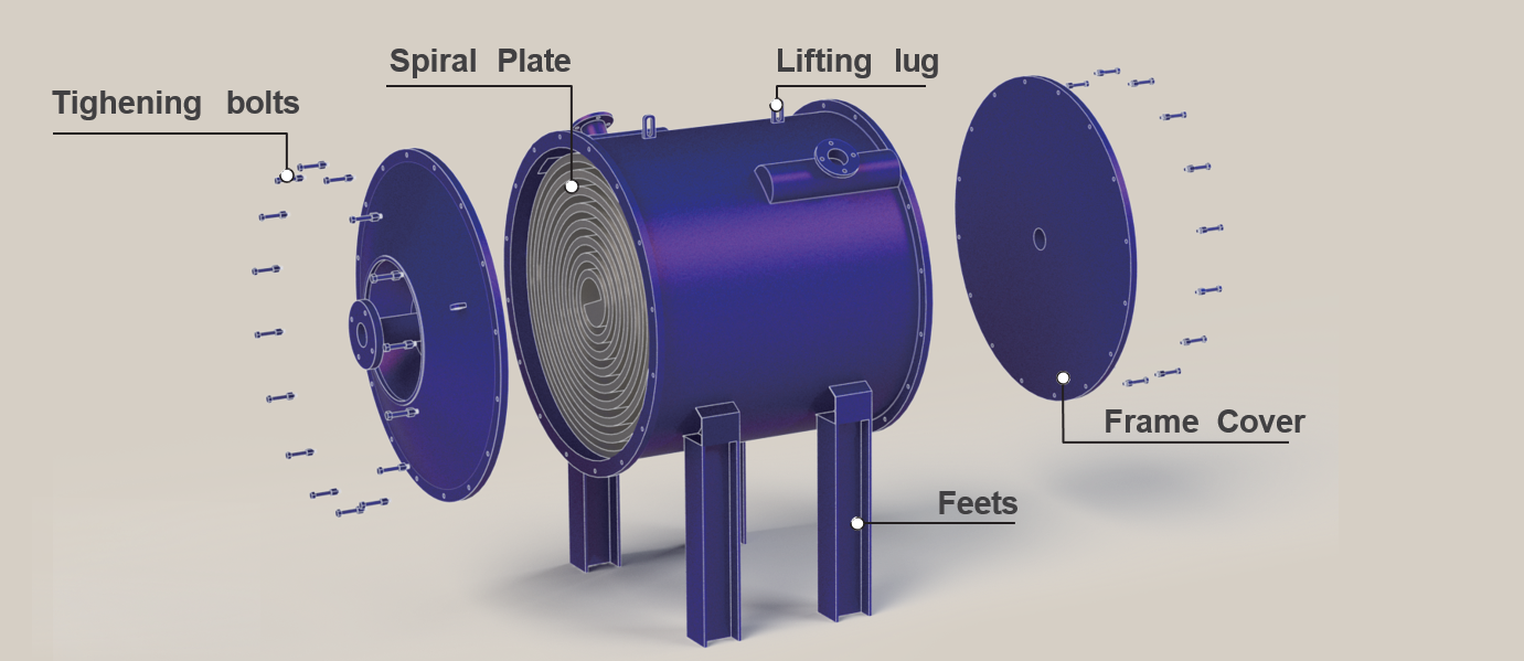
Exploded structure view: spiral plate pack, covers, bolts, lifting lug, and feet (use as your “structure” figure).
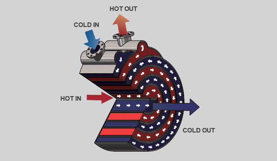
3) Working Principle (Counterflow in Continuous Spiral Channels)
SPHE typically operates in counter-current flow. Hot and cold fluids enter separate spiral channels and move in opposite directions,
maximizing the logarithmic mean temperature difference (LMTD) across the entire length.
Continuous path: reduces “dead zones” and improves heat transfer stability.
Curved flow + turbulence: helps suppress deposition and supports self-cleaning behavior for many services.
Single channel per side: prevents maldistribution common in multi-pass designs.
Flow principle: hot and cold streams travel through separate spiral channels, typically in counterflow.
4) Engineering Design: Parameters That Actually Matter
A reliable spiral heat exchanger design balances thermal duty, pressure drop, fouling behavior, and mechanical limits. The parameters below are the practical design levers used in sizing and engineering review.
Thicker plates support higher pressure but slightly reduce U-value
Channel spacing
Solids handling, turbulence, pressure drop
Wider channels reduce plugging risk; narrower increases heat transfer
Flow arrangement
LMTD, temperature approach, stability
Counterflow is standard for best approach temperature
Fouling allowance
Area margin, long-term performance
Set based on fluid nature: wastewater/sludge vs clean water
Nozzle sizing
Velocity, erosion risk, entrance losses
Keep velocities controlled for slurry/particulate services
Selection shortcut: if your service is “dirty + viscous + fouling,” prioritize channel spacing and cleaning access first—then optimize for duty and approach temperature.
5) Fabrication, Welding, and Quality Control
Spiral heat exchangers are typically fully welded. Fabrication quality directly affects leakage risk, pressure capability, and long-term reliability.
A standard manufacturing route includes:
Plate cutting and edge preparation
Stud/pin welding to control channel spacing
Spiral winding and channel sealing welds
Shell assembly, nozzle welding, and cover fit-up
Pressure test (hydrostatic) + leak inspection
Surface finishing and passivation (if required)
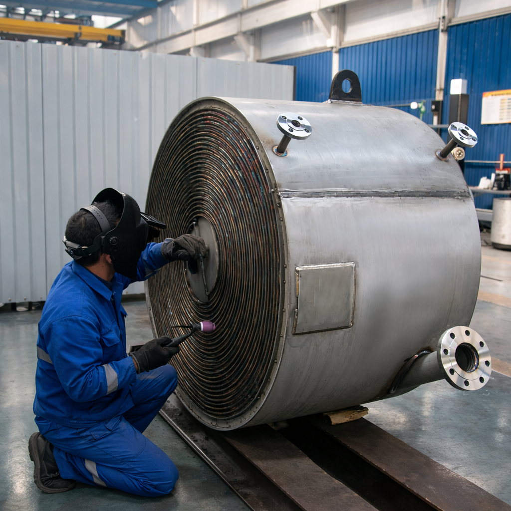
Channel weld quality and consistent fabrication practices are critical for pressure integrity and long-term reliability.Large SPHE unit inspection and finishing during assembly (good for “manufacturing capability” proof).
6) Typical Applications and When to Choose SPHE
Spiral heat exchangers are a strong fit for services where conventional exchangers face rapid fouling, unstable flow distribution, or frequent cleaning shutdowns.
Chemical processing: viscous liquids, polymer streams, contaminated cooling loops
Pulp & paper: black liquor and high-solids streams (case-dependent)
Heat recovery: dirty hot streams transferring to cleaner utility water
Simple selection checklist
Do you have solids or fiber in the fluid?
Is the viscosity high enough that tubes cause excessive pressure drop?
Do you need low fouling and easier access for cleaning?
Is a compact footprint important?
Engineering tip: For extremely plug-prone media, specify wider channels and conservative velocities. For cleaner services, you can tighten
channel spacing to increase U-value and reduce required area.
FAQ
Is a spiral heat exchanger self-cleaning?
Many services benefit from the continuous curved flow path that reduces stagnant zones and suppresses deposition. However, “self-cleaning” depends on solids type,
viscosity, temperature, and velocity. For severe fouling, design for access and planned cleaning.
How does SPHE compare with shell-and-tube for dirty fluids?
For dirty, fouling, or slurry services, SPHE often offers better stability and easier cleaning due to single-channel flow and minimized dead zones.
Shell-and-tube can be excellent for high-pressure or very high-temperature duties when fouling is low and mechanical constraints dominate.
What are the most important design inputs for SPHE sizing?
Duty, inlet/outlet temperatures, allowable pressure drop, fluid properties (viscosity/solids), fouling allowance, and corrosion requirements.
Channel spacing and material selection are usually the biggest practical levers.
Related Knowledge & Product Pages
Continue learning with closely related technologies and selection guides: