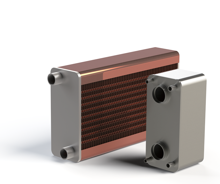
Compact brazed plate heat exchangers engineered to recover thermal energy from high-temperature flue gas into a liquid circuit for industrial and commercial heating systems.
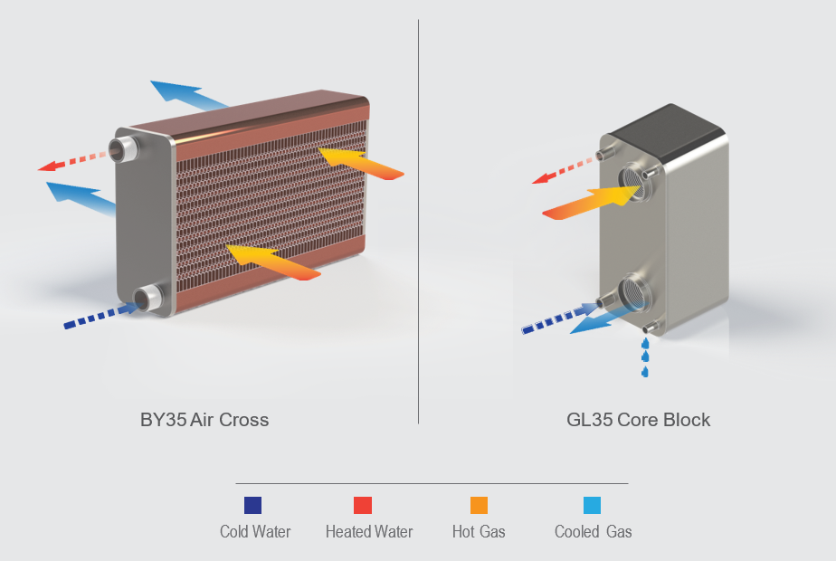
Hot gas and cold water travel through separate passages in counter-flow. The asymmetric gas channel handles the larger gas volume with low pressure loss, while corrugated stainless-steel plates transfer recovered heat into the liquid circuit. The outgoing gas is cooled and the water leaves at a higher temperature.
Published platforms
GL35 / BY35
Maximum design pressure
GL35: 20 bar; BY35: 15 bar
Temperature classes
250°C / 400°C / up to 750°C with selected materials
GL35 thickness E
4 + 4.0 × N mm
BY35 thickness E
6 + 3.2 × N mm
Primary design focus
Waste-heat recovery with low gas-side pressure drop
Engineering explained
See what is happening inside the exchanger.
Product imagery is paired with technical context so buyers and engineers can understand construction, flow path and configuration—not just the exterior.
01
Asymmetric gas and liquid flow paths
Large gas passages manage volume and pressure drop, while the liquid circuit uses compact corrugated channels to absorb recovered heat.
02
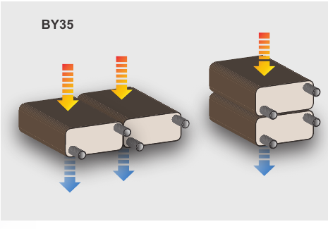
BY35 modular design
BY35 units can be combined horizontally or stacked vertically. Module quantity and arrangement are selected for gas flow, installation space and thermal-performance requirements.
03
GL35 flexible inlet and outlet configuration
GL35 gas connections can be located on the same side for a compact installation or on opposite sides for counter-flow and project-specific piping layouts.
Working principle · 3D animation
GL35: multi-pass heat recovery and condensation.
360° interactive view: Drag the model to inspect it from every angle.
Explore 4 mm channel depth for low gas-side flow resistance, internal multi-pass water flow and separate condensate drainage.
Conceptual application illustration. Final internal geometry and external piping follow project drawings.
Working principle · 3D animation
BY35: modular heat recovery.
360° interactive view: Drag the model to inspect it from every angle.
See modules stack and connect to common supply and return water headers.
Conceptual application illustration. Final internal geometry and external piping follow project drawings.
Models & technical data
Compare models and published specifications.
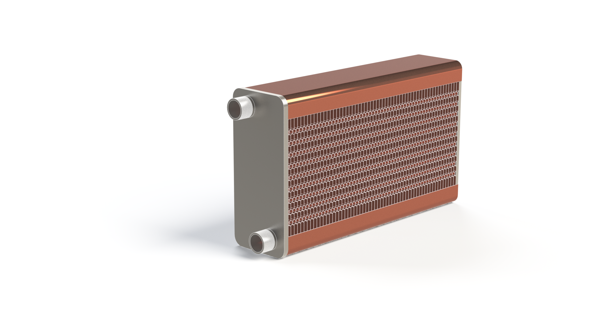
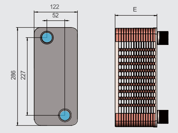
Compare circuit arrangement and overall dimensions at a glance, then open a product size for its product view, dimension drawing and technical summary.
Published HEXNOVAS family limits. N = plate count. The 750°C class requires selected material and project verification. Actual allowable pressure, temperature, corrosion resistance and gas-side fouling performance depend on final construction and duty.
Dimensions are for reference only. Final dimensions are subject to the approved order drawing. HEXNOVAS reserves the right of final interpretation.
Model details
GL35
HEXNOVAS Flue Gas Brazed Plate Heat Exchangers
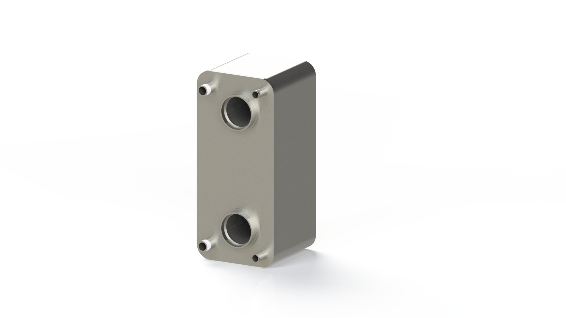
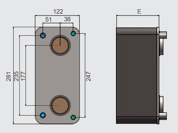
Product configurationDimension drawing
Circuit
Gas–liquid
Width (mm)
122 mm
Height (mm)
281 mm
Thickness E (mm)
4 + 4.0 × N
Max. pressure
20 bar
Temperature classes
250 / 400 / 750°C
Plate materials
304 / 316L / 904L
Bonding materials
Cu / SS / Ni
Plate material
SS304 / SS316L
Brazing material
Copper / nickel
Temperature range
-190°C to 200°C, configuration-dependent
Connections
Threaded, soldered or flanged
Dimensions are for reference only. Final dimensions are subject to the approved order drawing. HEXNOVAS reserves the right of final interpretation.
Provide gas composition, gas and liquid flow rates, inlet and target outlet temperatures, condensable and particulate content, allowable gas-side pressure drop, design pressure, material requirements, installation space and required inlet/outlet arrangement.
Frequently asked questions
Key questions before product selection.
How does Flue Gas Brazed Plate Heat Exchangers work?
Hot gas and cold water travel through separate passages in counter-flow. The asymmetric gas channel handles the larger gas volume with low pressure loss, while corrugated stainless-steel plates transfer recovered heat into the liquid circuit. The outgoing gas is cooled and the water leaves at a higher temperature.
What information is required to select the right product?
Provide gas composition, gas and liquid flow rates, inlet and target outlet temperatures, condensable and particulate content, allowable gas-side pressure drop, design pressure, material requirements, installation space and required inlet/outlet arrangement.
Which materials and configurations are available?
SS304, SS316L and 904L plate options; Copper, stainless or nickel bonding options; Project-specific high-temperature material selection
How is the final product size confirmed?
The final size is confirmed by thermal calculation using flow rates, inlet and outlet temperatures, allowable pressure drop, design pressure and fluid properties.
Product documentation
Catalogue and technical downloads.
Use the published catalogue for product-range reference. Final dimensions, ratings and materials are confirmed for the selected model and operating duty.